The four 24 volt
PV modules on the roof are grouped into two 48 volt pairs as described in
The solar panels article. The
+ and
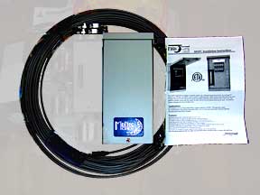
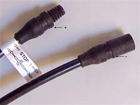
- cables from each pair descend from the roof and enter the combiner box. Two 50' MC-3 cables arrived with the combiner box. The connectors on each end come marked with a
+ (male) or a
- (female). I cut these two 50' cables into four 25' cables, two for each 48 volt module pair.
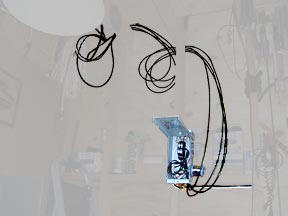
Before bringing the cables down I marked the cut ends with a
+ or a
- using white fingernail polish, a fast drying enamel. I also marked the cut ends with
East or
West in case I ever need to know that. If the connector on a cable was marked with a
-, I marked the opposite cut end with a
+. That way I would know which was which down inside the combiner box.
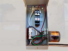
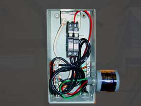
The
+ cable from each pair fits into the bottom of a dedicated 15 Amp breaker. The top of the breakers fit onto a common bus bar at the top of the box. The white neutral system wire runs from that bar out of the box to the
PV + connection in the
charge controller. The
- cables from all pairs connect to the
PV Negative bar on the left and the black 'hot' system wire runs from there to the
PV - connection in the charge controller. The
Ground bar on the right receives only ground wire from the system and the DC
lightning arrestor.